

Related: Part 1 - Tire PMs: Low-Tech Solutions for Cost Control
Electrical Systems: Proactive Measures for Protection
In part two of this six-part series, tips for maintaining electrical systems are shared, including helpful tools and best practices for battery maintenance and replacement.
by Bob Stanton, CPM, CPFP
March 6, 2017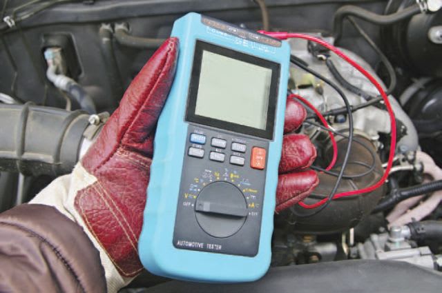
Using a voltmeter or
multimeter (pictured) is
necessary for checking
a battery’s charge. (Photo: iStockphoto.com)
5 min to read
Today’s truck is essentially a data engine. Part I of this series referenced OBD-II, telematics, electronic logging devices, and other data generators currently or soon to be on board. These tools — along with such others as two-way satellite communication common in road tractors, laptops, and onboard navigation systems — all have two things in common: Their reliability depends on the integrity of the truck’s electrical system and they all represent augmentation or added electrical loads not found on trucks five or 10 years ago. And yet, the capacity and characteristics of a truck’s electrical system has not changed in over 50 years!
In 1988, anticipating a technological revolution, the Society of Automotive Engineers (SAE) opened the dialogue on increasing the standard voltage on automotive and truck electrical systems. The dialogue continued throughout the 1990s and favored 42-volt systems. Fortunately for the benefit of our shop tools and employees, the industry engineered away the perceived need for higher voltage, leaving us with the 12-volt system we know and love. What has changed is the capacity, component efficiency, and engineering of a truck’s electrical system to accommodate higher load demands.
A further complication not often mentioned in discussions on electrical system maintenance and longevity is the high heat generated by engines equipped with selective catalytic reduction (SCR). Temperature (high heat or extreme cold) is among the most destructive elements jeopardizing electrical system integrity. Even when batteries are located outside of the engine compartment, several components, connectors, and wiring harnesses remain within that high heat space under the hood and can be subjected to the potentially damaging high temperatures routinely generated by SCR-equipped engines.
Of the many component systems inherent in trucks today, the electrical system is the most vulnerable, the most prone to breakdowns, and still the least understood. These facts all beg the question, have preventive maintenance (PM) procedures kept up? In spite of its 50-year-old architecture, the demands posed by today’s componentry have loaded the system like never before. Recognizing the importance, vulnerability, and necessity of electrical components, do our PM processes meet these challenges?
Electrical System Recognition
PM and routine maintenance processes that fail to recognize the interdependence of electrical system components are doomed. PM and routine maintenance processes that fail to incorporate the logical order of electrical component diagnosis are doomed. To many people, electricity is mysterious but in fact, electricity is logical, consistent, and even predictable.
The first step in updating electrical preventive maintenance processes is to recognize its components as one unified and interdependent system, rather than as individual components (e.g. battery, starter, and alternator). Even the National Institute for Automotive Service Excellence (ASE) exam recognizes this; the exam is called T6 Electrical/Electronic System (or A6 for automotive).
By approaching electrical as a system, the PM process can be tailored to check system componentry in a logical diagnostic order, thus avoiding component misdiagnosis and/or chasing the wrong problem.
Checking Batteries
Batteries are the heartbeat of the system; all checks begin here. Beyond cleaning terminals and connections, PMs should include the use of a voltmeter or at the very least a hydrometer to check the battery’s state of charge after the surface charge has been removed. Hopefully, the state of charge is 12.4-12.6 volts. If under that voltage, the battery should be charged to that state and rechecked. If overcharged, any number of causes is possible; all should be checked and corrected and the battery should be replaced. Do not simply replace the battery and expect the overcharge or undercharge condition to self-correct; it will not.
Testing Load
When the battery is fully charged, the next PM step is to perform a load test using a carbon pile or similarly capable testing device. Although many PMs don’t include this step, it’s really the only way to determine the true health of the battery because it does its work under load. The ATA’s Technology & Maintenance Council’s recommended PM practices include this step as do many trucking and transportation firms.
If a PM inspection checklist is utilized, adding the battery load test to the process and documenting it using a checklist will pay dividends in electrical system longevity and integrity.
Evaluating Voltage Drop
Another test, performed even less often, is a voltage drop test. This test is critically important in determining the health of the charging/starting system. Proficient and consistent utilization of this test performed on the starter and alternator will prevent premature and/or misdirected replacement of either component. Cable or connector resistance issues leading to decreases in voltage are often disguised and incorrectly diagnosed as alternator or starter failures. Adding “test cables” by truly testing them using a voltage drop test rather than relying on a cursory visual check will pay dividends in lower operational costs and breakdowns.
Replacing Batteries
A final word on battery replacements: technicians will often replace an entire battery set (two or four batteries) when the health of even one battery in that set is suspect. A best practice is for all removed batteries to be placed on a trickle charger for 24 hours and their state of charge rechecked. If the charge state recovers, those recovered batteries can be placed back in inventory at no charge and used as a new battery would be used. This practice will likely reduce new battery purchases by 30% or more.
Measuring Electrical System Maintenance
There is one place within any maintenance program where the relative effectiveness of the electrical system maintenance program can always be observed and evaluated. Whether there are concerns over electrical system maintenance costs, questions about the quality of the maintenance program, or questions about the rate of electrical system component replacement, do not inspect batteries currently installed. Instead, inspect the batteries, starters, and alternators located in the return/recovery/warranty areas of the shop or parts section for a visual reference of the program’s effectiveness.
Just as tire carcasses in the scrap pile will tell you all you need to know about your tire program, the batteries, starters, and alternators located in the return/rebuild/warranty or scrap areas will tell the story about the quality of the electrical system maintenance in any shop. They disclose replacement practices, maintenance quality, adherence to standards, warranty processes, battery age, etc. Further and perhaps in concert with your electrical parts supplier(s), these inspections, especially if done with a volt meter, can lead to program modifications that result in fewer replacements, greater component longevity, and lower costs overall.
The next installment in this series will cover suggested PM processes for aftertreatment systems.
About the Author:
Bob Stanton, CPM, CPFP is an independent fleet consultant and retired public sector fleet manager with 42 years of experience. He can be reached at victorybob@gmail.com.
Subscribe to Our Newsletter
More Maintenance

Linxup Expands Partnership with Fleetio to Bring Full Maintenance Management to Mid-Market Fleets
A new reseller partnership expands access to Linxup’s real-time GPS and telematics data with Fleetio’s leading fleet maintenance platform.
Read More →
Michelin Connected Fleet Expands Trailer Premium Solution
Michelin Connected Fleet’s Trailer Premium, designed for Class 7 and 8 fleet operators, detects metrics that affect tire longevity and alerts fleet managers to situations requiring tire inspection and/or preventive maintenance.
Read More →
Jasper Offers Remanufactured Chrysler 3.6L Pentastar Gen II Engine
The Jasper Engine & Transmission remanufactured Chrysler 3.6L Pentastar Gen II engine is now available and is covered by a nationwide, transferable, parts and labor warranty of up to 3 Years/100,000 miles.
Read More →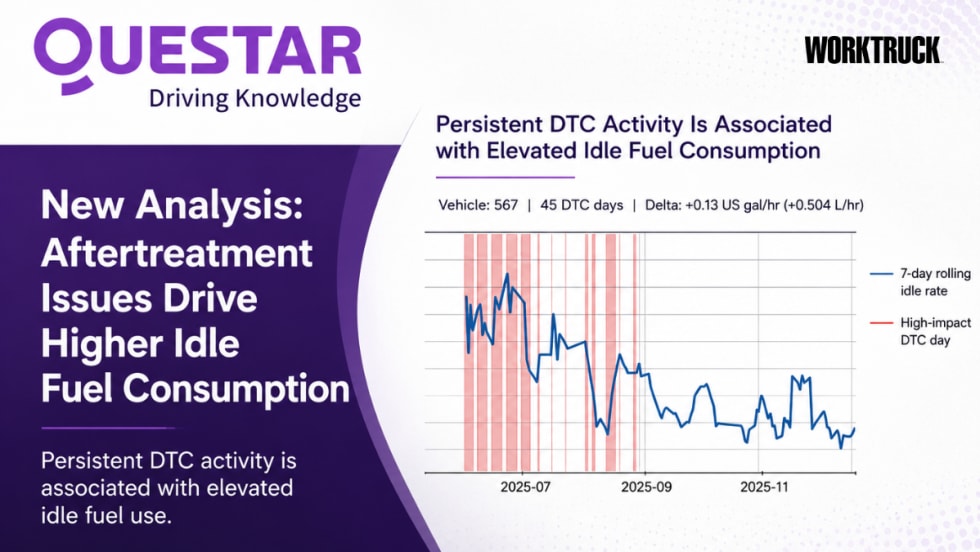
Questar Analysis Finds Aftertreatment Degradation Can Cost Fleets Up to $30 Per Vehicle Per Day in Excess Fuel
Questar analysis found degraded DPF and SCR systems can waste up to $30 in fuel per vehicle daily, creating significant avoidable fleet operating costs.
Read More →
ARI-hetra Launches 9,000-Pound Capacity Wireless Mobile Column Lift
ARI-hetra said its new lift is the industry's first 9,000-pound-capacity mobile column lift, delivering 36,000 pounds of total lifting capacity, ALI-certified safety, and reliable ball-screw performance for dealerships and medium-duty fleets.
Read More →
Where Are All the Women Technicians? Closing the Gap with Support and Career Pathways
Women make up just 4% of diesel tech roles. Here’s how trucking can attract, support, and retain more women in the shop.
Read More →
What REALLY Makes a Truck Reliable? We Want Your Input!
Work Truck is gathering real-world fleet insight on truck reliability. Share your experience and help shape upcoming editorial coverage.
Read More →
Hands-on Program at Yokohama’s Mississippi Truck Tire Plant Helps Employees Build Skills
Yokohama Tire Manufacturing Mississippi’s Maintenance Apprenticeship Program, in partnership with East Mississippi Community College, combines classroom instruction with on-site experience as employees pursue an associate degree.
Read More →Sponsored•May 29, 2026
Are You Tracking Your Fleet's True Total Cost of Ownership?
Bobit Business Media surveyed 190 fleet professionals and found that while most fleets are tracking costs, fragmented systems and data gaps are keeping true TCO visibility out of reach. With rising pressure to control spend in an increasingly volatile environment, the gap between what fleets think they know and what the data actually shows is wider than you might expect. See how your peers are managing costs today and where the industry still has room to improve.
Read More →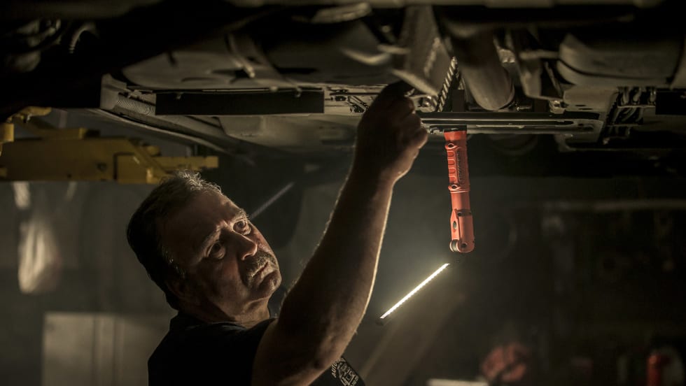
The Power of Inspection Lighting in Modern Fleet Maintenance
Technicians tackle varied tasks every day, but as problem-solvers, they need good illumination during inspections, repairs, and maintenance. So, what makes a good technician inspection light?
Read More →